Authored by Tony Feng
Created on Feb 16th, 2022
Last Modified on Feb 23th, 2022
Intro
This sereis of posts contains a summary of materials and readings from the course CSCI 1430 Computer Vision that I’ve taken @ Brown University. This course covers the topics of fundamentals of image formation, camera imaging geometry, feature detection and matching, stereo, motion estimation and tracking, image classification, scene understanding, and deep learning with neural networks. I posted these “Notes” (what I’ve learnt) for study and review only.
Parametric Transformation
It refers to a transformation $T$ is a coordinate-changing operation so that $p’ = T(p)$ for any point $p(x,y)$.
Common Transformations
- Translation
- Rotation
- Scaling
- Uniform scaling
- Non-uniform scaling
- Affine
- A combination of linear transformations, and translations
- Lines map to lines
- Parallel lines remain parallel
- Ratios are preserved
- Closed under composition
- Perspective
- Projective
- A combination of affine transformations, and projective warps
- Lines map to lines
- Parallel lines do not necessarily remain parallel
- Ratios are not preserved
- Closed under composition
- Models change of basis
- Projective matrix is defined up to a scale (8 degrees of freedom)

![]()
![]()
| Name | Matrix | Degree of Freedom |
|---|---|---|
| Translation | $\left [I \mid t \right ]_{2\times 3} $ | 2 |
| Rigid (Euclidean) | $\left [R \mid t \right ]_{2\times 3} $ | 3 |
| Similarity | $\left [sR \mid t \right ]_{2\times 3}$ | 4 |
| Affine | $\left [A \right ]_{2\times 3} $ | 6 |
| Projective | $\left [\bar{H} \right ]_{2\times 3} $ | 8 |
Camera Projection
Homogeneous Coordinates
It’s an an alternative coordinate system for projective geometry.
Converting to homogeneous coordinates
- 2D image coordinates $(x,y) \Rightarrow (x,y,1)$
- 3D scene coordinates $(x,y,z) \Rightarrow (x,y,z,1)$
Converting from homogeneous coordinates
- 2D image coordinates $(x,y,w) \Rightarrow (\frac{x}{w}, \frac{y}{w})$
- 3D scene coordinates $(x,y,z,w) \Rightarrow (\frac{x}{w}, \frac{y}{w}, \frac{z}{w})$
Scale Ambiguity


This means that no matter how we scale the projection space (i.e. the homogeneous coordinate representation), we do not change the underlying image represented by the coordinates.
Projection Matrix

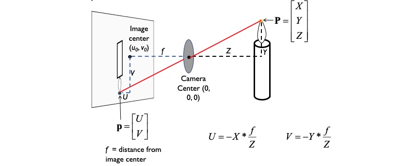
We want to find out where a 3D point $P$ in the scene will be located in the 2D image, and this diagram visualizes that process.
Intrinsic Matrix
Previously, we have 2 equations $x = \frac{fX}{Z}$ and $y = \frac{fY}{Z}$. They are not linear as we divide the coordinates by $Z$. But we can use homogeneous coordinates to manupulate the matrix to derive $x$, $y$ from $X$, $Y$, $Z$.
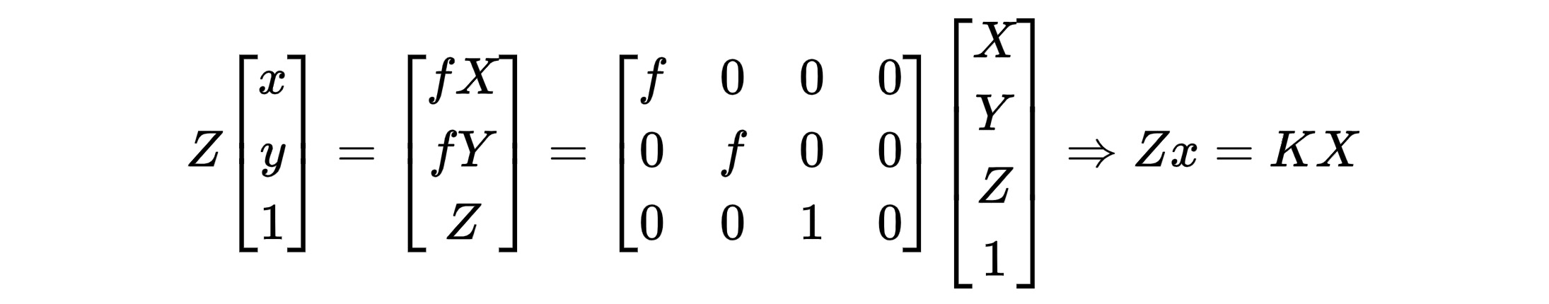
Here, $K$ is camera projection matrix, also called intrinsic matrix.
Assumptions
-
Optical Center: The above expression assumed that the origin in the image plane is at the principle point where the $Z$ axis hits the plane. It is not for most case. So, $x = \frac{fX}{Z}+u$ and $y = \frac{fY}{Z}+v$ should be considered.
-
Unit Aspect Ratio: Also, different camera sensors have different pixel physical pixel size. Hence, we need to find some way to convert focal length between physical size and pixels.
-
Skewness: We need to consider diagnal distortion of the image plane by adding the parameter $s$.
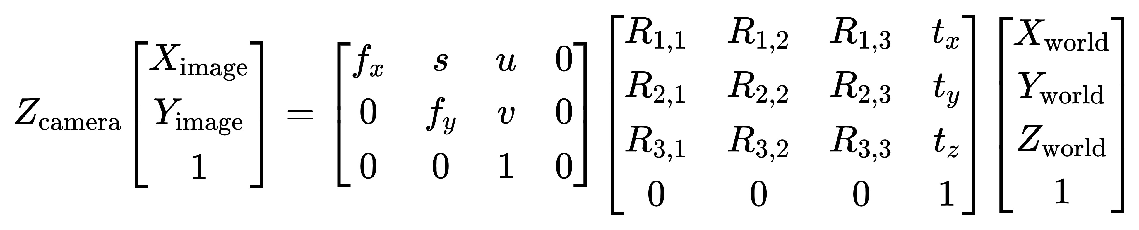
Now, we can obtain

Extrinsic Matrix
So far we assumed that the origin of the 3D coordinate system is located at the pinhole. Because camera may be far from the object and using the position of camera as orgin is not convenient, we like to use world coordinate system in reality to mark the location of an object. We can represent a world point in the camera’s coordinate system by considering the relation between the coordinates of $p$ in camera and world coordinate system.
$$x_{\text{camera}} = R(x_{\text{world}} - c) = Rx_{\text{world}} - RC = Rx_{\text{world}} - T $$

From World to Image Plane
- Transformation from world coordinates to camera coordinates
- Projection onto ideal image plane
- Applying radial lens distortion $x’ = \text{warp}(x)$
- Mapping to image plane to pixels
Here, intrinsic matrix has 5 DoF and extrinsic matrix has 6 DoF.